
The FPGA adventures
This post was inspired by the course - INTRODUCTION TO FPGA AND EMBEDDED SYSTEMS on Coursera from University of Boulder.


When I sit down to study electronics, it's always a conquest for me. It is like navigating in the pacific, facing storms and sharks. Although I have never sailed through the pacific, but I assume the probability of events are equally likely. As I explored FPGAs and HDLs in this thrilling expedition, I fled into the vastness of FPLDs- Field Programmable Logic Devices, and discovered a sense of logical understanding about them. Hence, I comprehend the same in this blog.
Before you go through the blog, I assume that you are familiar with the working of universal gates (NAND/NOR gates) and the some basics of PLAs and PLCs.
The FPGA family :
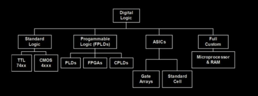
FPLDs are a breed of devices that execute complex logic, with necessary time constraints defined by the programmer/designer. They are further divided as PLDs, FPGAs, and CPLDs. They are efficient and equivalent to an ASICs - Application Specific Integrated Circuits, also compete with them in terms of functionality.
Defining FPGAs :

The ‘FPGA for dummies’ book defines, Field programmable gate arrays (FPGAs) are integrated circuits(ICs) that enable designers to program customized digital logic in the field. It has evolved from a useful but humble interface device into a system-level integrated circuit (IC) with its own microprocessors, memory blocks, and interfaces. It’s the next big thing. FPGAs have a variety of applications, from control functions to computations. Some of them are :
Single-Device Motor Control
Television Broadcasting
Wireless Data
Automotive Driver Assistance Cameras
High-Performance Computing
In future, I would prioritize the applications on their problem-solving abilities and spend more time.
FPGA Analogy :

The best analogies of an FPGA is explained using‘beads and strings’. No matter the complexity of the pattern, we can form any design given the number of beads and strings, with appropriate arrangements of the beads; also with different colours. That's how easy is an FPGA to implement any logical function. However, the taxonomy in FPGAs is a bit complex and precise, so we need to spend some time until we are familiar with the device. Some of the basic terms are detailed below :
Gates : AND and OR gates that are commonly used to implement Boolean expression.
Wires : The interconnections between the different gates and the memory element (Flip-Flops)
Flip-flops : The memory elements that are capable to store data for the corresponding inputs.
LUTs - Look Up tables : The tables from which the code is designed. It is from these tables, we design FPGAs to change their outputs with corresponding inputs.
Overall, FPGA designing involves the programming of gates and from the LUTs and interconnecting them to obtain desired outputs. Anyone familiar with C can understand Verilog and need not ponder other languages.
The HDL simulators are proven to be powerful tools using techniques like pipe-lining, can easily realize delays and produce accurate results. All I can further talk is influenced by a textbook : Verilog HDL, Samir Palnitkar. You can look it up anyway.